Product Details


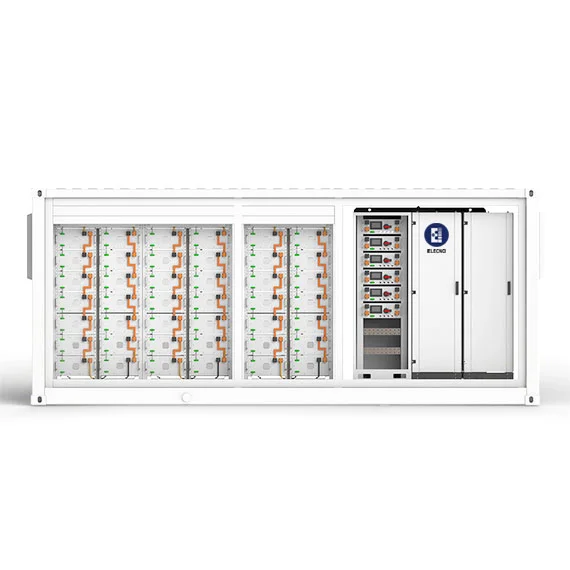
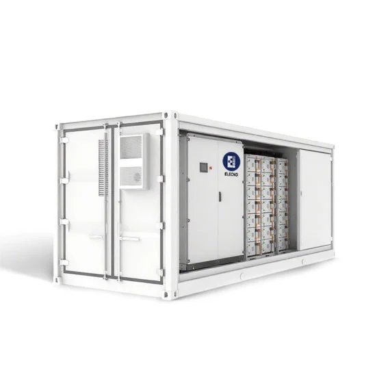
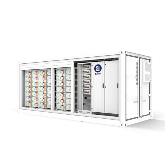
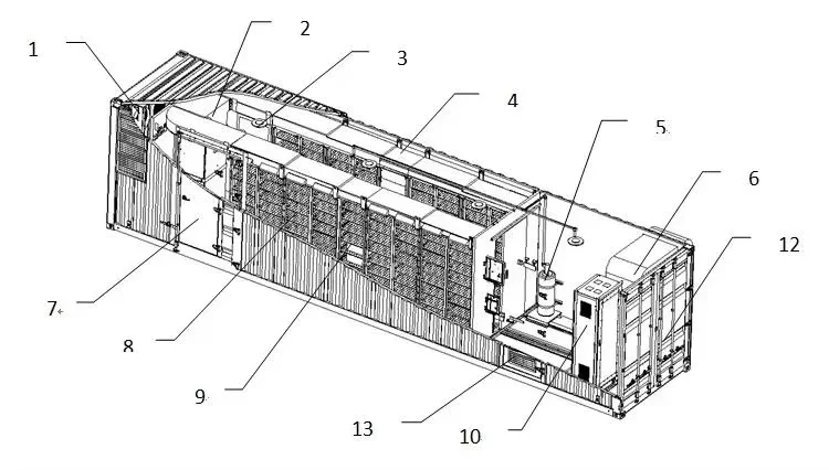
Containerized Battery Energy Storage System ESS is a high integrated solar generation and battery storage system. The energy storage system includes battery,inverter, PCS, thermal management, fire suppression, and smart controller.
A containerized battery energy storage system (BESS) integrates LiFePO4 battery racks, a battery management system, power conversion, thermal management, fire-safety equipment and controls inside a transportable 20ft or 40ft enclosure. The listed platform covers 1-4 MWh configurations for peak shaving, renewable integration, microgrids and backup projects; final usable energy, output power and supply scope must be confirmed on model-specific documents.
| Rated Capacity | 1MWh | 1.2MWh | 2MWh | 4MWh |
| Nominal Output Power | 500V | 600KW | 1MW | 2MW |
| Container size | 20HQ | 20HQ | 40HQ | 40HQ |
| IP Grade | IP54 | IP54 | IP54 | IP54 |
Specification note: This table is a product-family reference. Energy (MWh), output power (kW/MW) and electrical voltage (V) are different values; request a corrected, model-specific datasheet and single-line diagram before quotation approval.
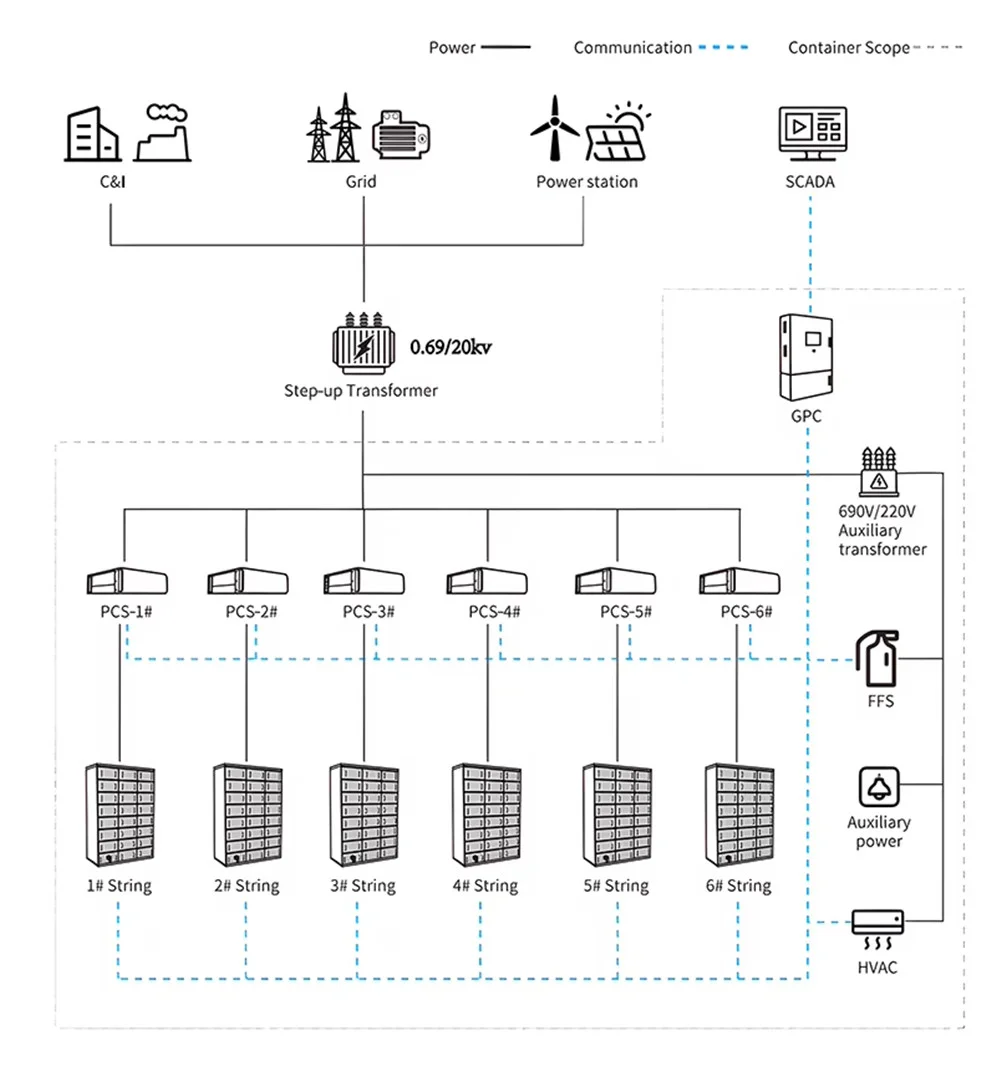
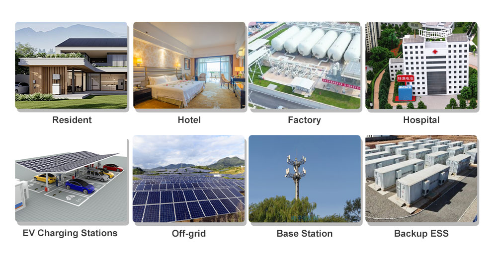
Our containerized battery energy storage system (BESS) is the perfect solution for large-scale energy storage projects.
Grid Stabilization and Frequency Regulation
Containerized BESS is crucial for integrating renewable energy sources like solar and wind into the grid.
BESS can maintain grid frequency and stability, preventing blackouts and ensuring reliable power supply.
Peak Shaving and Load Shifting
BESS can store energy during low-demand periods and release it during high-demand periods, optimizing energy use and reducing costs. It is suitable for microgrid system, such as industrial parks, commercial complexes, schools, etc.
Backup Power for Critical Infrastructure
Hospitals, data centers, and other critical infrastructure can benefit from the reliable backup power provided by containerized BESS. Energy storage containers can ensure uninterrupted operations of key equipments.
Remote and Off-grid Power Solutions
In remote areas where grid access is limited or non-existent, containerized battery energy storage system offer reliable and sustainable power storage solutions. They are particularly useful in disaster-stricken areas, where traditional power infrastructure may be damaged or non-existent.
Grid Support
Integrating energy storage containers with renewable energy sources can smooth renewable intermittency, offsets supply shut-downs, ramp rates, peak management, frequency regulations, voltage support, and rate arbitrage.
C&I energy storage system provide reliable power and energy storage for off-grid regular loads, grid-support cases and emergency back-up, with switchable energy input from renewable energy, a grid connection or diesel generator.
| Type | Features |
| LiFePO4 Battery | High energy density and long cycle life |
| Lead-acid Battery | Traditional and cost-effective, less efficient |
| Flow Battery | Utilize liquid electrolytes, ideal for large-scale storage with long discharge times |
| Flywheel Battery | Store energy in the form of kinetic energy, suitable for short-term storage and high-power applications |
A containerized battery energy storage system combines battery racks, BMS, PCS, thermal management, fire-safety equipment, controls and service access in a transportable enclosure. The listed product family covers 20HQ and 40HQ configurations for commercial, industrial, microgrid and renewable-energy projects.
In markets that use British English, the same product format may be described as a containerised BESS. Compare the exact usable MWh, PCS power, container layout, HVAC, fire-safety and commissioning scope rather than treating the spelling as a different system type.
| Decision area | 20ft / 20HQ planning | 40ft / 40HQ planning |
|---|---|---|
| Listed capacity range | The product-family table lists 1 MWh and 1.2 MWh variants. | The product-family table lists 2 MWh and 4 MWh variants. |
| Site fit | May suit tighter delivery routes, smaller foundations or phased projects. | May suit higher-capacity projects when transport, crane access and service clearance are available. |
| Internal layout | Confirm battery rack count, PCS location, HVAC, fire equipment, aisle and cable routing. | Confirm zoning, rack layout, thermal distribution, PCS/transformer boundary and maintenance aisle. |
| Shipping and lifting | Request final dimensions, gross weight, lifting points, center of gravity and unloading plan. | Check route restrictions, crane capacity, turning space, foundation and on-site positioning sequence. |
| Expansion | Define whether future capacity is added as another container or reserved inside the project design. | Define parallel-container controls, transformer capacity, protection and EMS coordination. |
Container length alone does not define usable energy, continuous power or project performance. Request an order-specific datasheet, single-line diagram and general arrangement drawing for the exact configuration.
| Scope | Information to confirm | Evidence to request |
|---|---|---|
| Battery system | Nominal and usable MWh, chemistry, SOC window, cycles, rack layout, BMS limits and degradation assumptions. | Model-specific datasheet, rack drawing, BMS architecture and warranty conditions. |
| PCS and grid interface | Continuous kW/MW, overload, AC voltage, reactive power, transformer, protection and grid-code assumptions. | Single-line diagram, PCS datasheet, protection list and responsibility matrix. |
| HVAC and auxiliaries | Design ambient range, heat load, airflow, redundancy, auxiliary power, condensation and maintenance access. | Thermal design basis, equipment schedule, alarm list and maintenance plan. |
| Fire-safety scope | Detection, ventilation, suppression, emergency stop, cause-and-effect logic and local interfaces. | Model-matched reports, drawings, alarm matrix and emergency information. |
| EMS and monitoring | Metering, dispatch logic, Modbus/Ethernet interfaces, user roles, alarms, data export and remote support. | Point list, screenshots, protocol notes and factory test records. |
| FAT and handover | Serial-number traceability, BMS/PCS communication, HVAC, alarms, emergency stop, packing and commissioning. | Approved FAT procedure, signed results, photo evidence and handover package. |
Safety and compliance requirements depend on the destination, authority and project design. The UL Solutions energy storage testing overview is a useful document-category reference, but it does not replace local engineering or approval.
Use the 20ft energy storage container checklist, the 40ft BESS layout checklist and the PCS sizing checklist, or send the project data for a configuration review.
A 20ft format may fit moderate capacity, tighter site access or phased deployment. The final decision depends on rack layout, PCS scope, HVAC, fire equipment, service aisle and delivery constraints.
A 40ft format may support higher capacity or more internal service space, but it requires a verified transport route, lifting plan, foundation and maintenance layout.
No. Battery energy in MWh and PCS power in MW are separate design values. Confirm both, together with overload, transformer and grid-interface requirements.
Approve final drawings, model-specific datasheets, safety documents, FAT scope, labels, serial numbers, packing list, shipping plan, commissioning procedure, warranty terms and responsibility boundaries.
For additional specifications, please get in touch with us. We are committed to providing comprehensive service