
Small Commercial and Industrial Energy Storage System Checklist
A small commercial and industrial energy storage system should be defined from the site’s operating problem, load evidence and electrical boundary before anyone selects a battery model. A shop, farm building, clinic, office, workshop or small warehouse may need backup for selected circuits, lower peak demand, greater use of on-site solar or coordinated operation with a generator. Those goals can lead to very different power ratings, energy capacity, control logic and supply scope even when the headline battery capacity looks similar.
This checklist is for owners, distributors, EPC teams and installers preparing an early design brief or supplier RFQ. It is not a construction design, financial forecast or live-work procedure. Final equipment ratings, protection, cable sizes, operating modes and installation details must be approved from site data, the selected equipment documents and the rules that apply at the project location.
1. Write one primary operating objective
Begin with the outcome that the site must achieve. “We need a battery” is not an operating objective. A clearer brief might say that selected refrigeration and point-of-sale circuits must continue through a defined outage, that the PCS should limit a measured grid-import peak, or that surplus daytime PV should support evening loads. If several objectives apply, rank them and state what happens when they compete.
For example, peak shaving can discharge the battery before an outage occurs, while backup service needs an energy reserve. Solar self-consumption may prioritize absorbing daytime PV, while a tariff-control strategy may reserve capacity for a different time window. The EMS cannot resolve these conflicts unless the owner defines priorities, reserve rules and the conditions under which an operating mode may change.
- Backup: list only the loads that must remain available, their required duration and the permitted transfer behavior.
- Peak shaving: identify the measured demand interval, target import limit and events the system must not create.
- Solar self-consumption: provide PV production and site-load data from comparable periods, including seasonal limits.
- Generator coordination: state whether the battery supports starting, load sharing, minimum generator loading or controlled shutdown.
- Future expansion: define a realistic expansion trigger and the electrical, communication and space provisions needed now.
2. Collect interval data, not only a monthly bill
A monthly electricity bill can show total consumption and tariff information, but it does not show when peaks occur, how long they last or which equipment causes them. Ask for interval load data at the finest practical resolution available from the utility meter, submeter, building system or temporary logger. Retain timestamps, units, missing-data notes, time-zone information and any production shutdowns or unusual events.
Then build a separate load register. Record each important load’s normal running power, start or inrush behavior, operating schedule, phase, voltage, power-quality sensitivity and whether it is essential during an outage. Motors, compressors, pumps, heating and cooling can create short power events that an average kWh figure hides. Network, controls and point-of-sale loads may be small but operationally critical.
Where peak reduction is the objective, the C&I ESS peak-shaving data checklist covers interval files, demand windows and dispatch limits in more detail. Keep the original data and document every cleaning or assumption so a supplier can reproduce the result.
3. Keep kW and kWh as separate decisions
Power in kW describes how much the system must deliver or absorb at one time. Energy in kWh describes how long that power can be sustained, subject to the permitted state-of-charge window and system losses. A project can have enough nominal kWh but still fail when simultaneous loads exceed PCS output or battery current limits. It can also have ample kW but too little usable energy for the required operating period.
| Design input | What it influences | Evidence to request | Common early mistake |
|---|---|---|---|
| Maximum simultaneous load | Continuous PCS or inverter power | Interval data and operating schedule | Using monthly kWh as a power value |
| Motor or compressor event | Overload, surge and protection behavior | Equipment data and measured event where available | Assuming nameplate running power covers starting |
| Required operating duration | Usable battery energy | Critical-load table and reserve policy | Equating nominal kWh with delivered AC energy |
| PV charging window | Charge power and daily energy balance | PV production, curtailment and load overlap | Promising full recharge from array nameplate alone |
| Future expansion | Parallel limits, bus, switchgear and space | Phased single-line diagram and equipment rules | Assuming any later battery can be added |
Separate nominal DC energy from usable DC energy and expected delivered AC energy. The differences can include the configured SOC window, reserve, temperature limits, conversion efficiency, auxiliary consumption and aging assumptions. Do not turn a first-pass division into guaranteed runtime. The earlier small commercial LiFePO4 battery sizing guide is the dedicated reference for capacity calculations; this article focuses on defining the complete project boundary around that calculation.
4. Decide whether the project is a battery component or a complete ESS
A battery enclosure is only one part of an operating storage system. The project may also need a PCS or inverter, EMS or local controller, revenue or control metering, protective devices, isolation, switchgear, transformer, HVAC, fire-safety interfaces, communications, auxiliary supply and a connection to PV, generator or backup loads. The RFQ should state which party designs, supplies, installs, configures, tests and warrants each item.
This distinction matters most near the boundary between a larger floor-mounted battery and a compact C&I cabinet. A component-level product may suit an installer that already controls the inverter, protection and commissioning package. An integrated cabinet may reduce interfaces, but it still does not automatically include the site transformer, utility protection, foundation, external cabling, fire-alarm integration or local approval work.
5. Use clear decision gates between a floor battery and a C&I cabinet
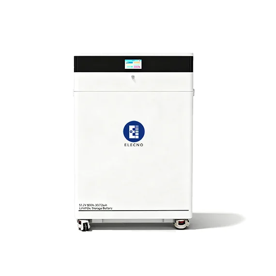
The current 51.2V 600Ah 30kWh floor-mounted LiFePO4 battery page lists a nominal 51.2V platform, CAN/RS485 communications and an intended larger-home or light-commercial use. It also tells buyers to confirm current limits, inverter protocol, firmware, usable energy, floor loading and indoor environmental conditions. That makes it a useful reference point, not a universal system answer.
Move the review toward an integrated C&I cabinet when the project needs higher power or energy, outdoor installation, coordinated thermal management, integrated PCS and EMS functions, a defined fire-safety package or a supplier-managed system interface. The threshold is not a single kWh number. Grid voltage, load type, continuous kW, installation environment, protection design, service access and the buyer’s ability to integrate components all matter.
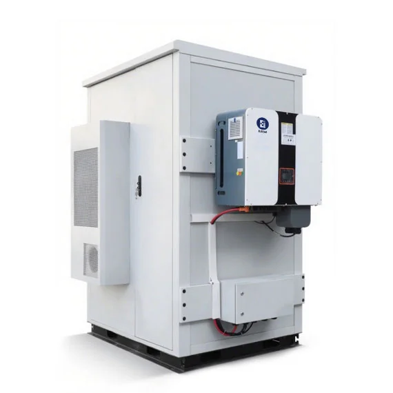
Compare the broader commercial and industrial energy storage range only after the decision inputs are written. If the project grows beyond a compact cabinet, review container layout, shipping and site integration as a separate stage instead of treating “larger” as a simple multiplier.
6. Draw the electrical and responsibility boundaries
Prepare a concept single-line diagram before requesting a final quotation. It should show the utility point, main switchboard, meter locations, PV, generator, essential-load board, PCS, battery, transformer where applicable, protective devices, emergency interfaces and communications. Mark nominal values as preliminary until the selected equipment and local design are approved.
Beside the diagram, create a responsibility matrix. For every interface, name the design owner, supplier, installer, commissioning party, test evidence and warranty boundary. This prevents a cabinet quotation from being interpreted as a complete installed plant when important site work is excluded.
| Scope item | Questions the RFQ must answer | Close-out evidence |
|---|---|---|
| Battery and BMS | Nominal and usable energy, current limits, SOC reserve, alarms, parallel rules and warranty assumptions | Model datasheet, configuration record and alarm test |
| PCS or inverter | Continuous kW, overload behavior, voltage, reactive-power capability, operating modes and protection interfaces | Approved settings, test results and event records |
| EMS and metering | Control objective, meter source, sampling, fallback mode, export limits, user access and data retention | Point list, screenshots, mode test and account handover |
| Site electrical work | Transformer, switchgear, cables, grounding, isolation, protection study and utility interface responsibility | As-built single-line, settings and inspection records |
| Environment and safety | Location, clearances, cooling, drainage, impact, corrosion, detection, emergency response and local approvals | Layout, manuals, inspections, training and acceptance records |
The PCS sizing checklist provides a deeper review of overload, reactive power and transformer limits. Use it after the load and connection data are available, not as a substitute for them.
7. Record the physical site before choosing the enclosure
Provide photographs, a dimensioned layout and the proposed cable route. Record indoor or outdoor location, ambient range, altitude, dust, humidity, flood exposure, corrosion environment, noise limit, access control, floor or foundation condition, service clearance, delivery route and lifting restrictions. State whether the area contains vehicles, stored materials, process heat, combustible hazards or public access that changes the site assessment.
Do not infer that an enclosure rating solves the whole installation. Cable entries, foundations, drainage, ventilation paths, collision protection and maintenance access remain site responsibilities unless the contract assigns them elsewhere. Similarly, a product’s listed temperature range is not proof that the complete system can deliver rated power continuously at every point in that range.
8. Treat safety and approvals as design inputs
Identify the authority having jurisdiction, utility requirements, applicable electrical and fire rules, required product evidence and the licensed or competent parties before freezing the equipment. The U.S. Department of Energy energy-storage resource provides public background on storage technologies and grid roles, while the OSHA electrical safety resource is a U.S. workplace starting point. Neither replaces the project’s local codes, manufacturer instructions or qualified engineering.
Ask the supplier for model- and configuration-specific documents rather than a generic certification list. The required package may include datasheets, manuals, drawings, component certificates or test reports, declarations, hazard information, transport documents, factory tests and commissioning procedures. Verify that document identities and revisions match the equipment offered. Never assume one certificate covers a changed cell, PCS, cabinet layout or market.
9. Define controls before asking for “smart” operation
Describe each EMS mode in plain language: what measurement starts the action, which limit it tries to hold, how reserve SOC is protected, what happens when communications fail and who can change settings. Specify meter location and ownership, time synchronization, data resolution, alarm routing, remote access, cybersecurity responsibility and the records required after handover.
Test conflicts deliberately. What happens if the peak target calls for discharge while backup reserve is low? Can PV charge the battery when export is limited? Does the system return safely after a meter or network failure? Is manual operation logged? The control narrative should answer these questions before the final point list and commissioning script are approved.
10. Send one supplier-ready RFQ package
A useful first package contains the site location, primary objective, interval data, load register, critical-load table, PV and generator information, grid voltage and connection details, concept single-line diagram, layout, environmental conditions, operating narrative, approval requirements and responsibility matrix. Add the target schedule, delivery boundary, FAT/SAT expectations, training, spare parts, remote support and warranty service location.
Ask every bidder to return the same comparison fields: usable kWh under stated assumptions, continuous and temporary kW, auxiliary consumption basis, PCS and battery limits, operating modes, included components, exclusions, drawings, evidence package, delivery terms, commissioning tasks and warranty conditions. The C&I ESS supplier qualification checklist helps review FAT, PCS and warranty evidence after the system boundary is stable.
For a configuration review, send the completed package through the SolarStorageHub contact page. A responsible response may request missing data before naming a model. That is preferable to a fast quotation built on an assumed load profile or an undefined installed scope.
Small commercial and industrial energy storage system FAQ
Is 30kWh enough for a small commercial site?
It can be suitable for some light-commercial profiles, but capacity alone cannot answer the question. Check the critical-load energy, simultaneous kW, start events, permitted SOC window, inverter efficiency, BMS limits, recharge plan and required reserve using measured or documented site data.
When should a project move from a floor battery to an integrated cabinet?
Consider an integrated cabinet when higher power or energy, outdoor installation, coordinated cooling, integrated PCS/EMS functions, a defined safety package or fewer component interfaces are required. There is no universal kWh threshold; the site, grid and integration responsibilities decide the boundary.
Can a monthly electricity bill size a C&I battery system?
No. It may support an early energy and tariff review, but it does not show short peaks, operating schedules, motor starts or critical circuits. Obtain interval data and a load register before confirming kW, kWh or runtime.
Does more battery kWh increase the system’s output power?
Not automatically. Output power also depends on the PCS or inverter rating, battery and BMS current limits, configuration, temperature, protection and operating settings. Power and energy must be checked separately.
What should be included in a small C&I ESS quotation?
The quotation should identify battery, BMS, PCS, EMS, metering, cooling, safety interfaces, enclosure, switchgear and transformer responsibilities, site work, shipping, FAT, SAT, commissioning, training, documents, exclusions and warranty conditions. Compare bids only after normalizing those boundaries.
Related SolarStorageHub Resources
If you are turning this article into a buying decision, compare the relevant product families and send your inverter model, target capacity, installation country, and quantity plan for confirmation.