
18kW Three-Phase Solar Inverter Installation Checklist: SLD, Breakers and Cable Sizing
An 18kW three-phase solar inverter installation should start with an approved single-line diagram (SLD), not a generic wiring picture. The design team must confirm the exact inverter model, grid voltage and earthing arrangement, rated and maximum currents, point of connection, protective devices, cable installation method, PV and battery interfaces, metering, shutdown functions and commissioning records before energization.
This checklist is for buyers, EPC teams, distributors and qualified installers reviewing an 18kW inverter package. It is not a model-specific wiring instruction and does not replace the manufacturer manual, utility approval, fault-level study, cable calculation, local electrical code or a licensed electrical designer. The rated power alone cannot determine a breaker, conductor or terminal connection.
What This 18kW Inverter Installation Checklist Covers
The checklist connects four documents that are often reviewed separately: the approved SLD, the protection schedule, the cable schedule and the commissioning plan. Those documents should describe the same inverter model and revision. If the SLD shows one neutral arrangement, the cable schedule shows another and the protection settings came from an older quotation, the package is not ready for installation.
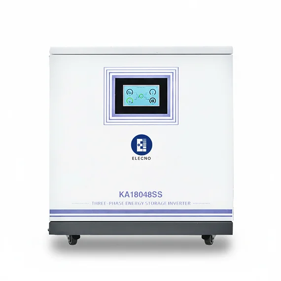
Use the 18kW high-frequency three-phase solar inverter product page to identify the quoted equipment, then request its current manual, data sheet, terminal schedule and approved options. For the wider buyer scope, compare the 18kW three-phase inverter factory and C&I ESS checklist. This article focuses on installation documents and release evidence rather than repeating product-selection advice.
Freeze the Site Data and Exact Inverter Model First
“18kW inverter” is not a complete installation specification. Two inverters with the same power rating can have different AC voltage ranges, neutral requirements, maximum output currents, PV string limits, battery interfaces, backup outputs, enclosure ratings and protective-device requirements. Record the full model code and manual revision on the design register and SLD.
The site data should include nominal and permitted grid voltage, frequency, phase arrangement, earthing system, prospective fault current at the point of connection, transformer data, existing main switchboard rating, export limit, available cable route, ambient temperature, grouping, installation method and utility interconnection conditions. If a battery is included, also freeze the battery voltage window, BMS protocol, maximum charge and discharge currents and approved shutdown sequence.
Build the Single-Line Diagram Around Every Electrical Interface
The SLD should show how the inverter connects to the actual project, not only a box labeled “inverter.” Identify the grid point of connection, main switchboard, inverter AC output, PV inputs, battery or DC source where applicable, meters and current transformers, backup or essential-load board, isolating devices, surge protection, earthing and communication interfaces that affect power control.
| SLD interface | Information to show | Review question |
|---|---|---|
| Grid connection | Voltage, phases, neutral arrangement, point of connection and main protective device. | Does it match the approved utility and site arrangement? |
| Inverter AC output | Exact model, conductor arrangement, isolator, breaker and protection references. | Are ratings linked to a calculation and manufacturer instructions? |
| PV input | String grouping, DC isolating method, polarity, voltage limits and surge-protection scope. | Does the array remain inside the inverter limits under site temperatures? |
| Battery interface | Battery model, DC protection, isolation, BMS communication and emergency shutdown boundary. | Is the battery-inverter combination explicitly approved? |
| Metering and control | Meter or CT location, direction, communication path and export-control function. | Can the commissioning team verify direction and fail-safe behavior? |
| Backup output | Transfer device, essential-load board, neutral treatment and interlocking. | Is unintended parallel operation prevented by the approved design? |
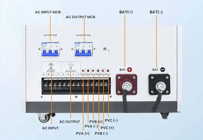
Keep detailed wiring and terminal numbers in the manufacturer drawing or project wiring diagram, referenced by document number and revision. A clean SLD should make protection and isolation boundaries understandable without becoming an unreadable copy of every control conductor.
Calculate Three-Phase AC Current Before Selecting Equipment
For a balanced three-phase system, a preliminary current relationship is I = P ÷ (√3 × V × power factor × efficiency). Use the applicable manufacturer-rated values and local design method. Do not treat 18kW as the current, and do not assume the same current at different line-to-line voltages. The inverter data sheet may state a maximum continuous output current that governs equipment selection more directly than a simplified calculation.
The design current is only one input. Check continuous operation, permitted overload, reactive-power operation, export-control modes, ambient derating, enclosure temperature, terminal limits and any utility-required operating range. Record assumptions beside the calculation so reviewers can see why the selected cable and protective device are suitable.
Coordinate Breakers, Isolators and Protection Functions
A breaker must protect the circuit and coordinate with the inverter, conductors, upstream switchgear and available fault current. Review rated current, poles, voltage, interrupting capacity, trip characteristics, ambient and enclosure derating, selectivity expectations and manufacturer requirements. An isolator must also have the correct voltage, current, duty and pole arrangement for the circuit it disconnects.
Do not choose a larger breaker simply to stop nuisance trips. First determine whether the trip is caused by an incorrect setting, unsuitable curve, temperature derating, cable limitation, upstream coordination, inverter behavior or a real fault. Protection settings and any residual-current function must follow the inverter topology, manufacturer instructions and local rules; a generic value from another model is not evidence.
The U.S. Department of Energy inverter and grid-services overview explains why modern inverters interact actively with voltage, frequency and grid functions. Project approval still depends on the local utility, jurisdiction and exact equipment.
Size AC Cables From the Installation Conditions
Cable sizing must consider design current, conductor material, insulation temperature rating, installation method, ambient temperature, grouping, route length, voltage drop, short-circuit withstand, protective-device clearing time, terminal temperature rating and mechanical protection. A conductor selected from current alone may fail the voltage-drop or fault-withstand check.
| Cable-sizing input | Evidence to retain | Common error |
|---|---|---|
| Design and maximum current | Manufacturer data and project calculation. | Using 18kW as though it were an ampere value. |
| Installation method | Tray, conduit, buried or free-air route drawing. | Using a free-air rating for grouped conductors in conduit. |
| Ambient and grouping | Site temperature and number of loaded circuits. | Ignoring derating inside a warm plant room or enclosure. |
| Voltage drop | Route length, conductor impedance and operating current. | Checking only ampacity on a long run. |
| Fault withstand | Fault level, clearing time and conductor calculation. | Assuming the normal-load calculation covers fault duty. |
| Termination | Terminal size, lug, torque method and conductor preparation. | Selecting a cable that does not fit the approved terminal system. |
Show AC phases, neutral when required and protective conductor separately in the schedule. The need for a neutral depends on the inverter and system topology; it should never be inferred from a photograph. Confirm cable glands, bend radius, segregation and strain relief before equipment arrives.
Plan Earthing, Bonding and Surge Protection as One System
The design should show the inverter protective-earth connection, enclosure bonding, equipment bonding conductors, earth bar, electrode or building earthing interface and the relationship between AC and DC surge-protection devices. Confirm conductor routes and termination points instead of relying on the enclosure mounting hardware as an assumed bond.
Surge protection depends on the site lightning-risk assessment, incoming services, PV layout, cable length, earthing arrangement and local requirements. Coordinate device type, voltage rating, location, backup protection and lead length. The article should not be used to select a surge device without those inputs.
Electrical work presents shock, arc and fire hazards. The OSHA electrical safety resource provides general U.S. workplace-safety context; the project must follow the laws, competency requirements and safe-work procedures of its own jurisdiction.
Check Phase Sequence, Phase Balance and Grid Quality
Before energization, verify the actual grid phase sequence against the inverter and metering scheme. Confirm CT phase assignment, CT direction, meter communication and export-control logic. A crossed CT or mismatched phase mapping can make the controller interpret import as export or assign power to the wrong phase.
An 18kW three-phase inverter may be designed for balanced output, while the connected building loads can be highly unbalanced. Record phase voltages and relevant load conditions, and confirm the manufacturer and utility limits for unbalance, voltage range, frequency, power factor and reactive-power functions. Do not claim that an inverter will correct site power-quality problems unless that function and operating limit are documented.
Separate Power Wiring From Battery, PV and Control Boundaries
The AC installation review should not hide DC and communication dependencies. Confirm PV open-circuit voltage across the design temperature range, MPPT grouping, DC polarity, isolation and connector compatibility. For battery systems, verify voltage window, maximum current, DC protection, pre-charge or startup sequence, emergency stop and the approved BMS protocol.
Use the 18kW inverter battery protocol and PV input checklist for those compatibility checks. The solar inverter and battery matching mistakes guide explains why connector fit does not prove voltage, current or CAN/RS485 compatibility.
Complete a Pre-Energization Document and Site Review
The pre-energization review should reconcile the installed equipment with the approved documents. Inspect identity and condition, conductor termination, gland and strain relief, protective bonding, isolator labeling, CT placement, communication wiring, enclosure sealing and required clearances. Record calibrated test equipment and results according to the approved method.
| Review stage | Minimum evidence | Release condition |
|---|---|---|
| Document review | Approved SLD, cable and protection schedules, manuals and utility conditions. | Documents agree on model, revision and interfaces. |
| Installation inspection | Identity photos, cable route, terminations, earthing, labels and enclosure checks. | No unresolved mismatch or unsafe incomplete work. |
| Electrical tests | Results required by the project method and local rules. | Results accepted by the authorized responsible person. |
| Settings review | Grid code, export limit, protection, battery and communication settings. | Settings match approved values and are backed up. |
| Functional test | Startup, shutdown, metering, alarms, control and operating-mode records. | Expected behavior is demonstrated and recorded. |
Do not energize to “see what happens” when the SLD, protection settings or conductor identities are unresolved. Use a controlled release signed by the authorized project role. The hybrid solar inverter commissioning checklist provides a separate path for CT direction, export limiting and battery-protocol tests.
Record Commissioning Results and Handover Evidence
Commissioning records should identify the inverter serial number, firmware where relevant, final settings, test equipment, date, personnel and approved configuration. Capture grid voltage and phase sequence, meter and CT verification, startup and shutdown behavior, alarms, communications, export-control response and battery or PV operation within the tested scope.
Handover should include the approved as-built SLD, cable and protection schedules, settings backup, test records, utility approval where required, manuals, warranty conditions, maintenance access and an open-item list. Use the solar battery installer resources guide to connect the site survey, drawing approval, commissioning and final customer package.
Information to Send With the RFQ
Send the supplier or engineering team the destination market, exact grid voltage and frequency, phase and neutral arrangement, utility export rules, PV array data, battery model where applicable, required backup function, point-of-connection drawing, cable route, ambient conditions, enclosure location, communication needs and target commissioning date.
Request the exact data sheet, manual, terminal drawing, protection requirements, certificates applicable to the quoted model, communication documentation and warranty boundaries. Compare wider options through the Solar Inverter category and use the Battery Storage Buyer Resources hub for related technical checklists.
18kW Three-Phase Solar Inverter Installation FAQ
Is the AC current of every 18kW three-phase inverter the same?
No. Current depends on line-to-line voltage, power factor, efficiency, operating mode and the manufacturer-rated maximum output current. Use the exact model data and project voltage.
Can an installer copy a generic 18kW inverter wiring diagram?
No. A generic diagram may have a different grid arrangement, neutral treatment, PV or battery interface, terminal order and protection scope. Use an approved project SLD and the current model-specific manual.
How should the AC breaker be selected?
Selection should consider the inverter maximum current, conductor capacity, continuous duty, derating, poles, voltage, fault interrupting capacity, trip behavior, coordination and manufacturer and local requirements.
Does a three-phase inverter always need a neutral conductor?
No universal answer applies. Neutral requirements depend on the inverter topology, grid and earthing arrangement, backup function and manufacturer instructions. The approved SLD must show the required conductor arrangement.
What determines the AC cable size?
Design current, installation method, ambient temperature, grouping, voltage drop, fault withstand, route length, conductor material, insulation rating, terminal limits and local rules all matter.
What should be verified before first energization?
Verify equipment identity, approved drawings, protection and cable schedules, earthing, conductor terminations, phase sequence, CT direction, settings, required test results, labels, enclosure condition and authorized release.
Who approves connection of an 18kW inverter to the grid?
The responsible utility, network operator or authority and the licensed project professionals determine the required approval path in the installation jurisdiction. Supplier documentation alone is not grid-connection approval.
Final Installation Release Rule
Release the installation only when the exact inverter, approved SLD, protection schedule, cable calculation, earthing plan, grid settings and commissioning records describe the same completed system. Keep assumptions and revisions visible. For a project-specific document review, send SolarStorageHub the inverter model, grid data, battery or PV scope and available SLD.
Related SolarStorageHub Resources
If you are turning this article into a buying decision, compare the relevant product families and send your inverter model, target capacity, installation country, and quantity plan for confirmation.